A Comprehensive Guide to Jointing Busbars: Which Method is Best?
May 8, 2023 9:52 am
There are many situations where it is necessary to join two busbars to create a single, unified unit. This process, called “jointing,” may be needed to create a longer busbar from shorter, more manageable pieces; or to create a T-shaped tap-off connection from the main busbar.
The result of jointing must simultaneously meet multiple objectives. It must be mechanically strong, be resistant to environmental stress, maintain performance over time and load cycles, and of course, ensure good electrical performance in the form of low resistance. As with all technical processes, there are options in how to meet the objective and subtleties in doing so. For busbars, the available options are:
- Bolted
- Clamped
- Riveted
- Solder or Brazed
- Welded
(Special considerations apply to flexible braided and laminated busbars; these are discussed in the sidebar at the end)
- Bolted joints are created by overlapping the bars and then inserting bolts through holes in the overlapping area, with flat washers under both the bolt head and nut sides to spread the load, Figures 1 and 2. They are reliable when properly prepared and torqued but require that holes be made in the bar, either by drilling or punching.
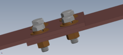
The bolted connection does not provide perfectly uniform contact pressure across the joint and the bolts induce some distortion in the current-flow path. These modest shortcomings can easily be accommodated, for example, by using larger washers to provide more-consistent pressure across the joint for mechanical and electrical integrity. A practical advantage of bolted jointing is that it can easily be assembled in the field.
2. Clamped joints also begin with an overlap between the two busbars. However, instead of bolt holes and bolts, external clamps are applied around the joint to create nearly uniform contact pressure and mechanical integrity, Figures 3 and 4.
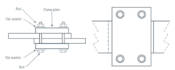
Figure 3: Clamped Busbar Joint
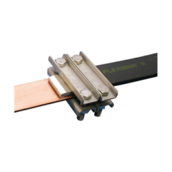
Figure 4: Clamped Busbar and Flexible Busbar
There is no bolt to act as an obstacle to current flow and the clamp mass helps to moderate temperature changes during ebbs and flows in current levels. A properly designed and installed clamp requires more space than a bolted joint does but does not need any holes, thus simplifying the fabrication process.
3. Riveted joints are prepared the same way as bolted joints with holes through the bars but with rivets used in place of bolts, Figure 5.
Although they cannot loosen like a bolt, they are more difficult to install, and controlling the contact pressure is a challenge. Also, they cannot be easily tightened or adjusted once installed, nor can they be easily dismantled – although that may be a benefit in some situations. Riveting is a good fit for volume-production situations such as fabricating busbars for electric mobility.
joints begin with overlapping of the busbars, as with the previous jointing options, and results in a low-resistance joint, Figure 6. However, heating of the joint during use due to high currents can affect mechanical and electrical reliability,'
- Soldered or Brazed joints begin with overlapping of the busbars, as with the previous jointing options, and results in a low-resistance joint, Figure 6. However, heating of the joint during use due to high currents can affect mechanical and electrical reliability,
Figure 6: Soldered Joint
- Welded joints require overlap, unlike soldered or brazed joints. Instead, the ends of the two bus bars are butted and welded, Figure 7. This merged busbar requires no more space than the single bar, and the is unimpeded by bolts. However, it is a challenge to actually fabricate this joint on-site, due to the actual installation setting.
Figure 7: Welded Joint
Minimizing joint resistance
Since bolted and clamped jointing are the most common techniques, it’s important to examine their performance characteristics in more detail.
The electrical objective of any jointing is to minimize and maintain contact resistance. Two factors affect the joint contact resistance: the “spreading resistance” also called “streamline effect” due to the distortion of the current flow path as current is diverted through the joint; and the contact resistance itself.
Analysis shows that the consequences of the streamline effect fall off rapidly once the overlap length is five times the thickness of busbar. This is not a problem in practice, as the overlap length needed for bolting or clamping is usually at least that much.
Analysis also shows that placing the bolts in a straight line, such as two rows of two or three bolts, is preferable to staggering and offsetting the bolt positions, Figure 8. This is because there is less disturbance to the path of the current flow.
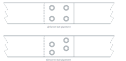
Figure 8: Offset Bolting Busbar Joint
Finally, angling or chamfering the ends of the busbars reduces current-flow disturbance, Figure 9. The greatest benefit occurs if the . Doing so also reduces localized hot spots and thus decreases the rate of increase in resistance that can develop due to current cycling.
Figure 9: Angled or Chamfered Busbar Joint
Managing contact resistance
Contact resistance is primarily a function of the condition of the busbar surfaces where they overlap and the total applied pressure. Although the busbar surfaces may look smooth and flat, when viewed on a microscopic scale they really have tiny hills and valleys such that the actual contact area is only about 1% of the overlap area. The amount of contact areas can be increased by ensuring that the busbars are flat and – somewhat counterintuitive – roughing the surfaces to remove the accumulated oxide layers. As contact area is increased, more of the peaks will make contact and also break though remaining oxide, resulting in more direct metal-to-metal contact.
It may seem that plating of copper busbar surfaces will improve contact situation. However, it may be counterproductive as the softer plating material may flow slightly at higher temperatures, leading to reduced contact pressure.
As expected, contact resistance decreases rapidly with increasing pressure, but only up to a limit where it reaches a point of diminishing returns. Also, there is a difference in applying pressure via bolted joints compared to clamped joints.
For the bolted case, the pressure is obviously applied immediately around the bolt holes. Therefore, using more bolts and large, thick, non-deforming washers will spread the load and provide a more-uniform pressure profile. In contrast, clamp bolts transfer the pressure to an area outside the width of the conductors. Therefore, the actual pressure at the overlapped joint depends on the rigidity of the clamps, and clamps across wider busbars may not provide the needed rigidity.
Bolt material, applied torque, and thermal considerations also play large roles. The optimal torque value must provide sufficient contact pressure at ambient temperature, yet it must not exceed the maximum stress (proof or yield) for the bolt material over the temperature range that the joint may experience. Among the choices for bolt material are galvanized steel, copper alloy, high tensile steel, stainless steel, and aluminum bronze.
Depending on their relative values, the difference in thermal expansion between the bolt and bar materials may increase or decrease the contact pressure. The maximum tension in the bolt over operating temperature must be kept below the yield stress of the bolt, to ensure it does not undergo plastic deformation which would result in loosening of the joint and sub-design performance. If this is a concern, a Belleville washer (disc spring) in conjunction with the flat washer can reduce the bolt tension if the differential expansion increases it.
Another technique for reducing contact resistance is to cut a longitudinal slot in both busbars, Figure. This relieves reduces the localized contact-pressure differences and instead increases its uniformity across the contact area, Figures 10 and 11.
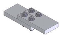
Figure 10: Slotted bolted connection
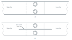
Figure 11: Slotted busbar jointing
Although contact resistance is just a small fraction of the overall busbar resistance in nearly all situations, it still has important implications beyond the immediate voltage drop and associated power-loss inefficiency. First, the temperature increase is highly localized and will cause expansion/contraction cycles at the joint zones. This will have a long-term effect on joint reliability with the possibility of tiny cycle-induced fractures which will subsequently grow. Second, the busbar joints, for T-jointing, are often located in and so will increase the local heat load and its effects on nearby electronic systems.
Clamped joints have many similar design criteria and consideration as bolted joints, but there are some unique considerations. First, the clamping plates must be thick enough so they effectively transfer the clamping pressure without flexing. One simple solution is to use ribbed rather than flat clamp surfaces. Second, the temperature across the clamp is not uniform, with its edges cooler than the bar it is clamping. As a result, the uneven expansion of the clamp due to temperature rise may result in the clamp pressure increasing beyond the design value.
Joint degradation
Even a properly designed and installed joint is subject to degradation via various mechanisms. The good and bad news is that these are generally slow-moving phenomena until contact resistance crosses some threshold. At that point, the degradation accelerates and actually can reach a self-reinforcing runaway mode.
Since the negative consequences of degradation usually do not become apparent until it nears the limit of acceptable performance, regular monitoring of the joints may be needed. This is usually implemented by looking at temperature as well as its rate-of-rise at the joints.
Degradation mechanisms include:
- Oxidation of the metal-to-metal contact surfaces. Cleaning and roughing of the surface areas before assembling the joint is effective at minimizing this. In some cases, adding a filler such as petroleum jelly around the contact to block oxygen penetration will also slow the process.
- Corrosion occurs when an electrochemical reaction occurs between the metal busbar surface and the ambient environment. Again, fillers can help here.
- Fretting is accelerated damage at the surface of the busbar materials where they contact each other. It occurs when the material surfaces undergo tiny cyclic, back-and-forth movement with respect to each other. Fretting amplitude is typically below 100 nanometers and is caused by vibration, thermal cycles, and even small load changes.
The mechanisms of fretting are not fully understood, but this motion causes surface wear and even micro welds, which in turn lead to additional oxidation and wear as they tear away. Eventually, the wear debris and hard surface particles that form result in an insulating layer between what were previously metal-to-metal contact.
- The result is in extreme cases, creep and stress relaxation can cause the joint to fail.
In addition to thermal cycles causing pressure and resistance cycles across the joint, often with detrimental long-term effects, the temperature change will cause dimensional changes along the length (longitudinal aspect) of the busbars. Depending on the specifics of busbar length, range of temperature, and installation geometry, it may be necessary to include a flexible element in the busbar arrangement.
Conclusion
Planning and executing a low-resistance, effective, reliable jointing of busbars requires analysis of electrical, mechanical, thermal, and material-property considerations. The effects of temperature change and especially rise is an important factor in the selection and engineering of the joint. There are many viable approaches as well as the inevitable tradeoffs to assess when developing and implementing a jointing design solution that meets performance and reliability objectives.
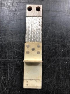
Flexible and laminated bus bars are used where the installation has a tight fit or must accommodate constant vibration or motion. Jointing these bars brings additional issues which must be considered.
The most common types of flexible cable are braided and multilayer (also referred to as laminated). Multilayer busbars are built up from multiple layers of thin sheets with a thicker outside layer on each side. They usually have insulation between their layers and can also have a surrounding extruded jacket similar to a wire cable.
This assembly can be riveted (the earliest construction technique), Sidebar Figure 1. A more-recent technique is press welding, where the laminations are welded to each other through direct current applied to the pieces under pressure to form an assembly with the properties of a plain, solid bar.
Bus Bars | by Storm Power Team
Comments are closed here.