Exploring Busbar Joint Resistance: A study on the Effects of Torque and Plating
January 29, 2024 8:10 am
By: Storm Power Components
A study shows the effect of surface-plating material and bolt torque on busbar contact resistance, a critical parameter in high-current connections.
Designers, installers, and users know that for high-current busbars handling hundreds and thousands of amps, it’s details such as contact resistance which are critical, as even a few micro-ohms (1 micro-ohm (µΩ) = one millionth/10-6 of an ohm) is significant. At these extremely high current levels, every additional micro-ohm of contact resistance at a joint or connector brings two undesired consequences: significant voltage losses due IR drop across the resistance (V = IR), along with Joule self-heating (P = I2R) which degrades the joint and induces thermal stress due to expansion (and even subsequent contraction) as a result of power cycling, Figure 1.
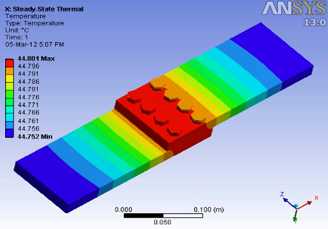
Figure 1: ANSYS modeling of Joule self-heating due to resistance at the bolted busbar joint shows resultant localized thermal gradients along the busbar. (Image source: IEEE via Semantic Scholar)
The Dilemma
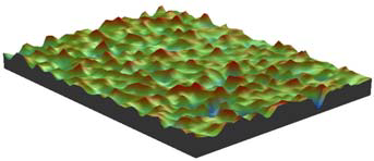
In addition to contact design, two factors that have a major impact on the resistance of bolted busbar joints are plating finish and bolted torque. Real contact surfaces are not perfectly flat but actually have many microscopic “hills and valleys” called asperities, which result in the actual surface-to-surface contact area being much less than the apparent size.
The reduced contact area, which is the result of these highly localized, small cold-weld contacts are bottlenecks in the conducting paths for the current flow, Figure 2.
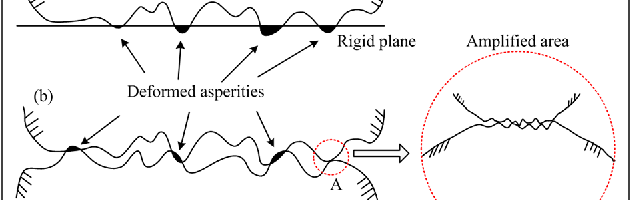
Figure 2: Microscopic asperities in the contacting surfaces (left) result in actual current flow paths which are much smaller than the apparent surface contact area (right). (Image sources: Advances in Mechanical Engineering via Semantic Scholar; IEEE via ResearchGate)
The result is much higher contact resistance than expected by a simple, broad surface-area calculation. The real contact area is often referred to as “conducting contact area” is only a fraction of the apparent contact area. It can range from a few percent to 80% of the apparent area depending on material type, hardness, contact force, surface cleanliness, and other factors. It will change will use as the bolted contact area heats due to current flow and resultant Joule self-heating, aging, and exposure to local environmental conditions.
The tests
In response to a customer inquiry, engineers at Storm Power Components (Decatur, TN) — a custom bus bar manufacturer and supplier supporting industries from telecom, generators, and rail to radar systems and aerospace — set up and ran tests to compare the effects of finish and torque on the customer’s bolted connection. The test sample consisted of an upper part bolted to lower part via an M6x1 tapped hole, Figure 3. The tests consisted of measuring the average resistance with different surface finishes on the parts and torques on the hex-head bolt and flat washer.
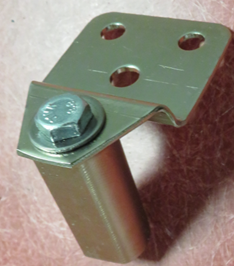
Figure 3: This customer-supplied assembly was used for the contact-resistance tests. (Image source: Storm Power Components)
The tests varied two factors:
- Finish: copper plated with:
1) electrolytic nickel per ASTM B689, type 2, class 5 ($0.35/assembly)
2) silver with a nickel strike undercoat per ASTM B700, type 1, Grade D, Class T ($1.58/assembly); both with comparable plating thickness
- Torque:
1) 4 newton-meters (Nm)
2) 9 Nm
A specialized test instrument, the Megger DLRO10HDX Digital Low-Resistance Micro-Ohmmeter and its probes, was used to measure the micro-ohm resistance levels, Figure 4. This unit can drive up to ten amps into the contact resistance being assessed for resistance values up to 250 milliohm (mΩ), above the values of interest here). This high drive current assures adequate IR drop across the resistance for a valid measurement.
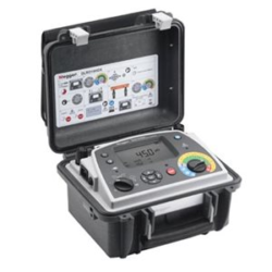
Figure 4: The Megger DLRO10HDX was used for the micro-ohm resistance measurements; it is specifically designed for such ultralow-resistance evaluation. (Image source: Megger Group Limited)
The Test Results
The data showed that both finish and torque play a significant role in contributing to shifts in the average micro-ohm readings. However, torque was a major factor only if nickel was used, Figure 5.
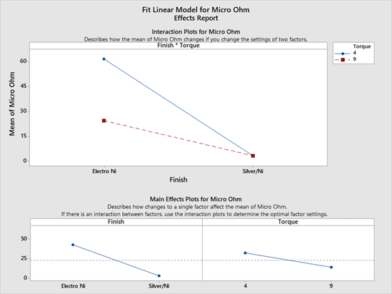
Figure 5: The test results show that both finish and torque affect resistance shifts, but the torque was a meaningful factor only for the nickel finish. (Image source: Storm Power Components)
Together, torque and finish were responsible for about 86% of the observed variation in contact resistance, which dropped as low as 3 micro-ohms, Figure 6.
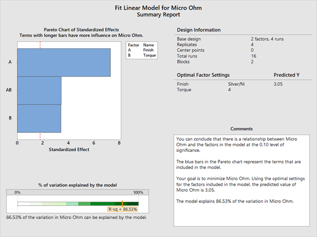
Figure 6: Contact resistance dropped to a few micro-ohms, with torque and finish accounting for the bulk of the variation with a high level of confidence and significance. (Image source: Storm Power Components)
Based on these tests, the engineers concluded that ASTM B700 silver with a nickel strike undercoat will achieve the lowest average resistance, and that four newton-meters of torque will provide nearly the same resistance as more than doubling it to nine newton-meters.
References
- IEEE Transactions on Components and Packaging Technologies, “Effect of Connection Design on the Contact Resistance of High Power Overlapping Bolted Joints” (2002)
- Journal of Engineering Mechanics, “Stress-Dependent Electrical Contact Resistance at Fractal Rough Surfaces” (2015)
- MEMSWAVE Workshop (Barcelona, Spain), “Effect of Contact Force Between Rough Surfaces on Real Contact Area and Electrical Contact Resistance” (2007)
- Science Direct/2021 International Conference on New Energy and Power Engineering, “Design of DC transmission busbar connection of CRAFT”
- Advances in Mechanical Engineering, “Normal contact stiffness of rough surfaces considering oblique asperity contact,” (2019)
Bus Bars | by Storm Power Team
Comments are closed here.