Laminated Bus Bars:
January 15, 2021 12:02 pm
Design, Fabrication, and Testing Expertise Are Keys to Performance, Reliability
The laminated bus bar (LBB) is a passive component which is used in many systems to carry power and even signals between multiple points with minimal voltage drop, power loss, and inductance. This laminated bus bar has multiple conducting layers of copper or aluminum separated by adhesive-coated insulating dielectric film. The conducting and interposed dielectric lamination layers are carefully bonded together by heat and pressure to create the final assembly as a single merged unit which can take many flat or even formed shapes, Figure 1.

Figure 1: Laminated bus bars are fabricated as basic flat shapes but also can be formed to meet the unique space constraints of the design.
Laminated bus bars address two power-related design challenges: they significantly reduce voltage drop due to IR loss in high-current power-distribution systems, and their very low stray inductance minimizes a possible cause of instability and output oscillation in switching power supplies. Depending on size and thickness, laminated bus bars can support voltages and currents ranging from low, single-digit values up to hundreds of volts and amps and even higher. These bus bars are a clean, clear, and direct mechanical solution to a problem defined by electrical engineering realities, and can even provide some relief to heat-dissipation issues.
Designs Driven by Each Customer’s Unique Needs
At first look, laminated bus bars appear to be fairly basic mechanical assemblies made up from only a few distinct parts, with little complexity in design and needing only a few final assembly steps. However, designing and fabricating a laminated bus bar that meets project requirements and has short- and long-term reliability requires expertise, skills, attention to detail, and careful testing.
Laminated bus bars can be designed with wide range of sizes and configurations. Short, lower-capacity laminations can be easily manufactured for small- and medium-size PC boards and circuits that only need to handle the lower power levels and have few spacing or installation constraints. However, there are many applications which need the unique, tailored electric capabilities and mechanical form factors which only a custom design can deliver.
Among the many material and design choices to be considered when meeting the multiple priorities of end-use applications are these:
- Bus bar conductor material: usually copper (but can also be aluminum) and sizing (height, thickness, needed to meet the basic electrical requirements.
- Dielectric (insulation) types: among the options are PET (Mylar®), Kapton®, Nomex®, and epoxy powder coat, each with different electrical and mechanical attributes with respect to thickness, dielectric strength, maximum operating temperature, cost, and other factors.
- Interlayer adhesive layer on the dielectric: must also be selected to match the application parameters, again including temperature.
- Possible use of insulating washers between layers in the bus-assembly design.
Of course, the design and fabrication must also meet multiple safety and performance standards, including creepage (over surface) and clearance (through air) requirements for the intended operating voltage.
Manufacturing, Fabrication Expertise Also Critical
Despite the simple concept of the laminated bus bar, manufacturing a reliable, quality component requires experience with respect to obvious and not-obvious issues. It’s the attention to small but critical details that assures a high-performance laminated bus bar with consistent long-term performance and reliability. Among these are:
- Deburring of all metal edges;
- Planarity of the individual metal layers;
- Precise alignment and interconnection of multiple layers, maintaining minimum creepage and clearance dimensions;
• Adherence to the lamination pressure standards with optimum heating and cooling cycle profiles, using a high-performance press, Figure 2.
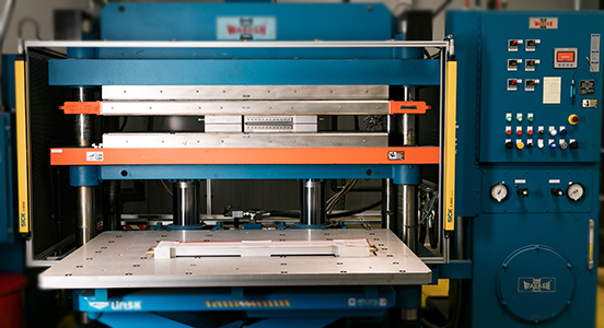
Figure 2: The lamination process requires careful control of the ramp up and down of both the heat and pressure cycles for optimum and reliable results.
- Application of appropriate customer-specified edge treatment, including open, pinch, epoxy fill, Figure 3.
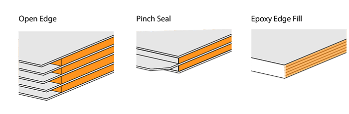
Figure 3: Users have a choice of laminated-layer edge treatments which offer tradeoffs in performance, size, and other factors.
Electrical Tests Provide Confidence, Assurance, Regulatory Adherence
Even a basic component such as laminated bus bar needs multiple electrical tests to verify there are no material, manufacturing, or latent defects. The demands on today’s laminated bus bars are constantly increasing due to added electrical-system stress with higher voltages and currents using silicon carbide (SiC) and gallium nitride (GaN) semiconductors in power subsystems in products such as electric or hybrid vehicles, and data centers/server farms with hundreds of amps per rack.
Comprehensive tests are used to verify manufacturing quality and assure longer-term performance, which can easily range up to 20 or more years in industrial, automotive, or traction-motor applications. These tests can uncover problems due to issues such as dielectric pinholes, voids, cracks, and impurities; conductor burrs, misalignment, misassemble, contamination; and more.
There are three standard tests required by good engineering practice as well as regulatory guidelines. Fortunately, these tests are non-destructive and so can be done on every laminated bus bar for 100% quality assurance, rather than just verification by production sampling. While there is some overlap among these tests, each provides insight on the immediate electrical condition of laminated bus bar as manufactured and also on potential future issues of the assembly.
The three tests, which are performed between physically adjacent layers of the completed assembly, are:
- High potential (hipot) test;
- Partial discharge (PD) test;
- Insulation-resistance test (often called a megaohm or “megger” test).
In brief:
- The hipot test, formally called a dielectric strength test, stresses the insulation and ensures that no current flows from one lamination to another lamination (it is the opposite of a continuity test), Figure 4. International Electrotechnical Commission (IEC) standard IEC 60950 mandates that the voltage used for the hipot test be twice the maximum operating voltage plus an additional 1000 volts (the 1000 V is added since the insulation in any product can be subject to transient overvoltages).

Figure 4: The dielectric strength test applies a specified high voltage across the conducting layers and checks for current flow between them.
The test voltage generated by hipot test equipment is not turned on abruptly. Instead, it is ramped up smoothly from zero to the final value over a one-minute period to allow the inherent capacitance between laminations to absorb charge and stabilize, at which point the testing begins.
- The partial discharge test, finds small electrical “sparks” – localized dielectric breakdowns – that occur within the insulation of medium- and high-voltage conductors. These discharges result from electrical breakdowns (ionization) in air pockets within insulating layers, which may be due to microvoids or partial delamination. The associated currents are generally short-duration events with rise times on the order of microseconds or even nanoseconds. The partial discharge test is an early indicator of the possibility that such discharges erode insulation and eventually result in insulation failure over the long term. Figure 5.
There are many ways to set up and initiate partial discharges for test purposes, including those defined by various UL and IEC standards such as IEC 60270. Among them is the application of a high-voltage frequency sweep to the unit under test, which responds as a resonant circuit. The resonant frequency will shift slightly as a partial discharge occurs and the layer-to-layer capacitance changes. Other approaches measure the change in impedance which occurs when there is a partial discharge event in the laminated bus bar.

Figure 5: The partial discharge test detects electrical breakdowns tiny voids between layers and is an early indicator of possible long-term problems.
- The megaohm testing uses a megohmmeter (often called a “megger”) to impose a high DC voltage between conducting layers, then measures the associated very high resistance, Figure 6.

Figure 6: The megaohm test measures the layer-to-layer resistance after a high DC voltage is applied across adjacent layers.
The high voltage is typically between 500 to 1500 VDC and is applied for a specific time period. The test reading is usually taken one minute after the high voltage is applied, again to allow capacitive and absorption currents to stabilize. Since the testing is for lamination insulation integrity, there should be little or no current flow between the conductors and a high resistance value is expected – typically 35 to 100 megohms (MΩ). The insulation resistance is also a function of temperature, so these tests are usually done at 20°C or 40°C (if they are done at a different temperature, a standardized correction factor is applied).
Note that a megger measures insulation resistance while a hipot test measures the closely related parameter of leakage current. The hipot test stresses the insulation’s weak points at higher voltage levels than the megger does, so if a fault is seen with the megger, it will also be seen with the hipot test.
These three tests provide multiple independent perspectives of the electrical quality of the fabricated laminated bus bar. They also point to “hidden” issues which may become faults after years of use and stress. The result is that the customer has solid assurance of initial quality as well as likely long-term reliability
Conclusion
Even though the laminated bus bar appears to a simple mechanical design which solves an electrical problem by using basic materials of conductors and insulating layers with clear fabrication steps, it is actually much more than that. A quality laminated bus bar is not a “quick and easy” design or fabrication, even if it may look that way. Expertise, skill, and a set of post-production tests are key factors that a knowledgeable, multi-faceted vendor brings to the product.
For more information view our Laminated Bus Bar Guide.
Bus Bars | by Storm Power Team
Comments are closed here.